Brunnshög, Lund, Sweden · Lund University, 2024
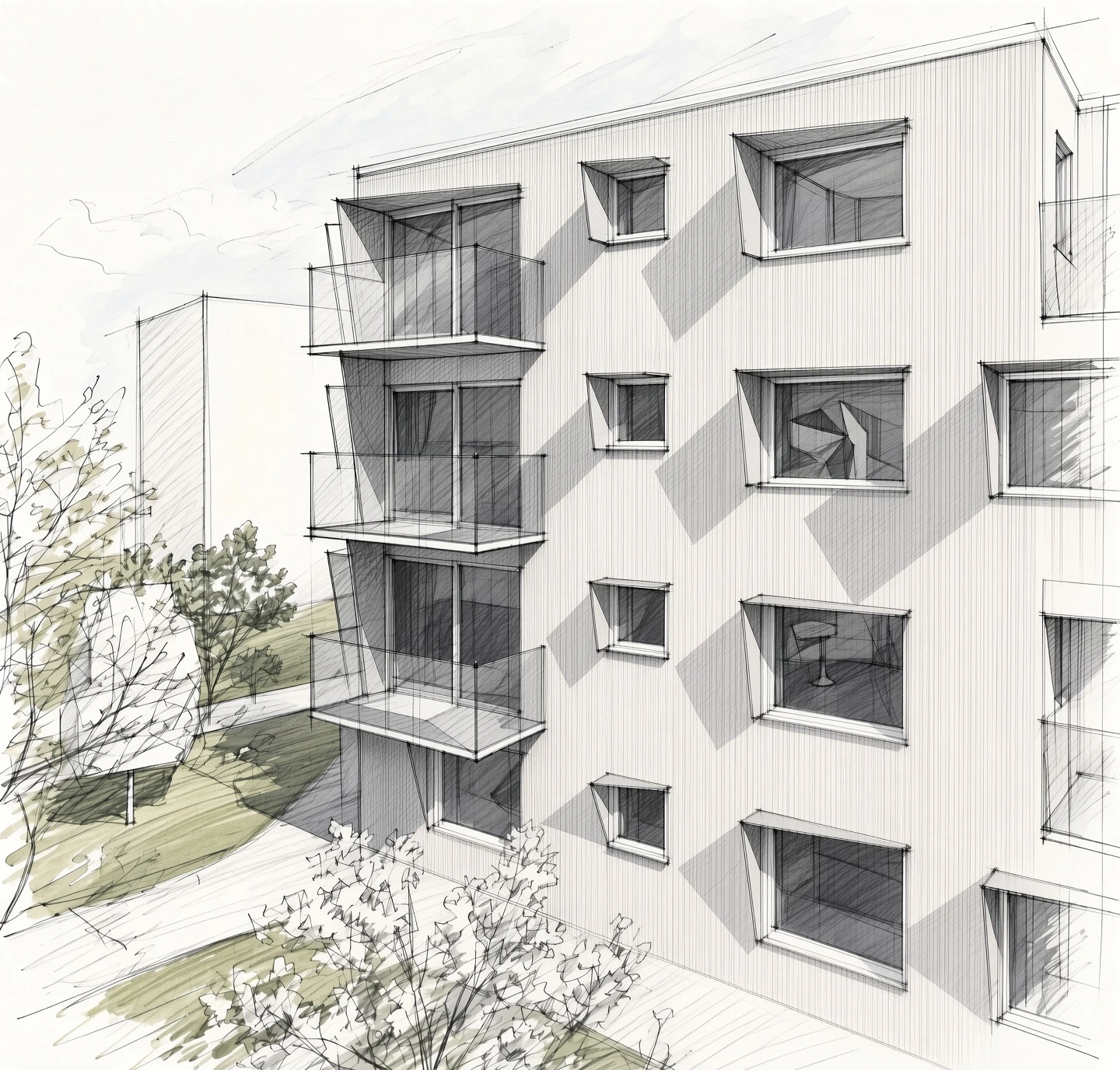
Residential building to passive house standard
Integrating thermal and moisture aspects
Three sites in Brunnshög, one of the expanding neighbourhoods of Lund, were given for a multi-storey residential building of about 900 m² heated floor area. Number of floors, orientation and shape were left open, so the design itself became the first result: site and form were each chosen by simulating alternatives.
26
kWh/m²·a heating demand — the BBR limit is 35
< 10 %
of the time above 26 °C, the FEBY12 requirement
≤ 0.03
mould index in every layer, VTT model
Aim of the project
To design a multi-storey residential building in Lund, Sweden: energy-efficient towards passive house criteria, moisture-safe, and meeting the indoor thermal comfort requirements.
Brief
The cold, humid climate of southern Sweden sets two requirements against each other: the envelope has to capture as much winter sun as possible without overheating the apartments in summer, and it has to stay airtight and free of mould over its service life.
Apart from fitting the height of its context, the design was left open, so every step was decided by comparing alternatives rather than by assumption — site, volume, glazing and shading were each simulated, and every construction assembly was verified for moisture before it was accepted.
My contribution
Group project with Elena Boyadzhieva and Denis Kosovac. My work packages:
- Preliminary energy simulation and comparison of options
- Study of window-to-wall ratio, glazing properties and shading against heating demand and thermal comfort
- Hand calculation for the foundation slab
- Roof assembly for the final design
Approach
01
Site selection
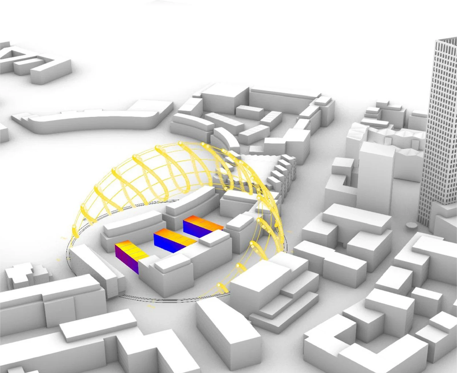
The northernmost site receives the most direct sun and needs the least heating.
- Sun path, irradiation and direct sun hours studied for all three given sites.
- One identical test building simulated on each site to compare them.
- Northernmost site selected — least shaded by the surrounding blocks.
02
Volume studies
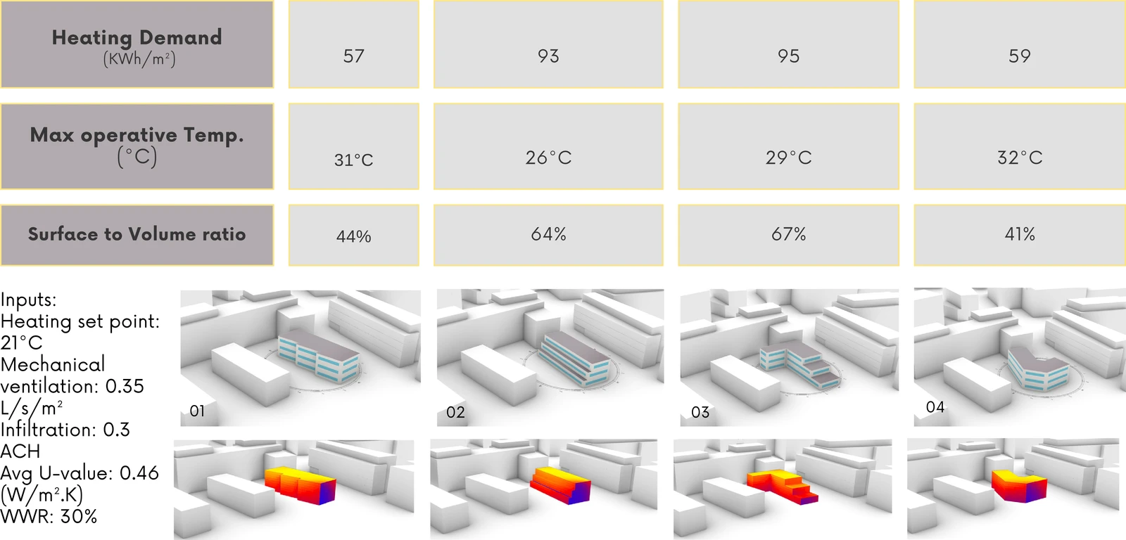
Compactness drives the heating demand — every added external wall costs energy.
- Rectangular bar, L-shape, stepped volume and V-shape tested on the chosen site.
- Compared by heating demand, maximum operative temperature and surface-to-volume ratio.
- Four storeys chosen: at the same heated area, the most compact of the tested heights.
03
Chosen form
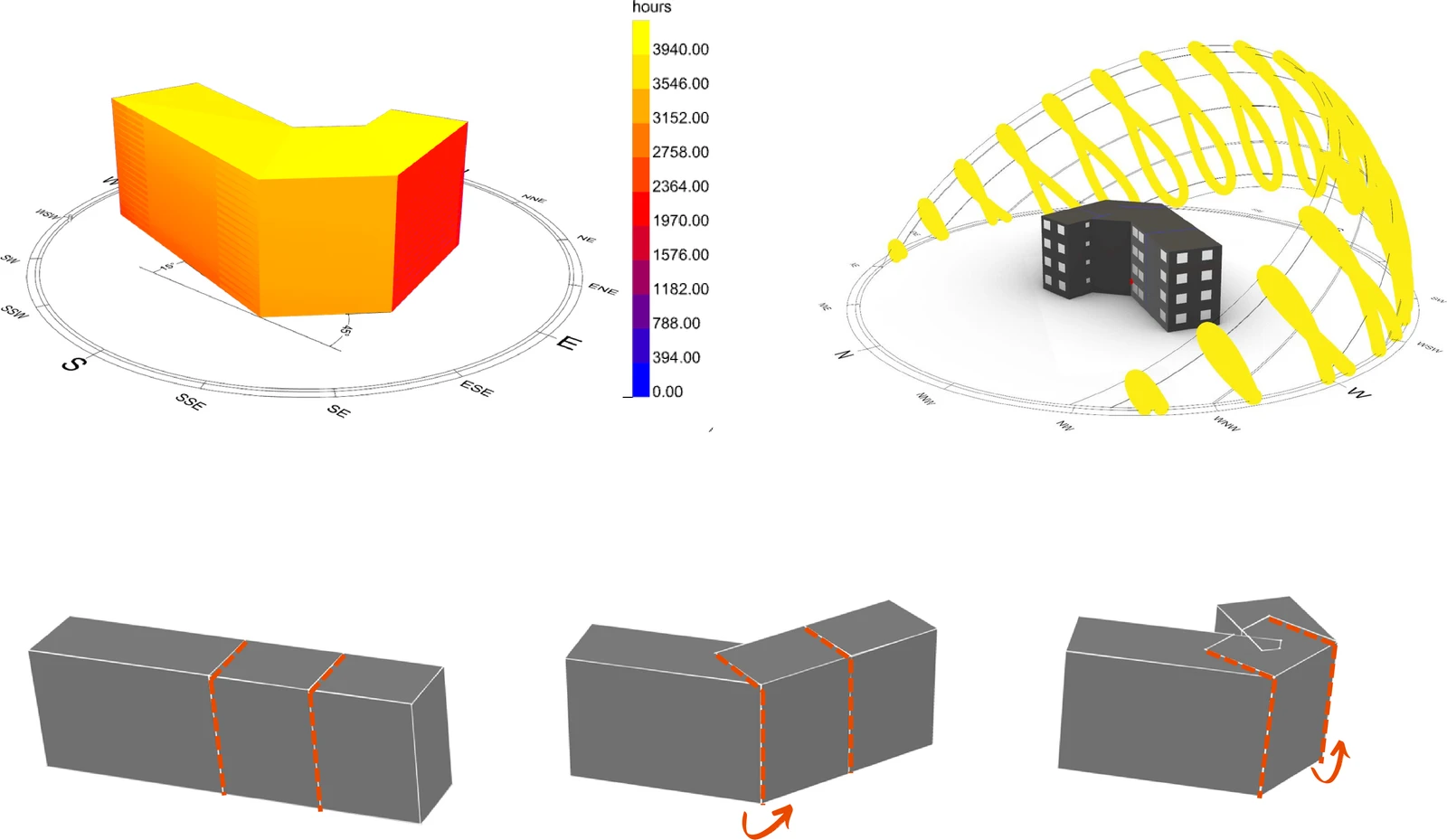
A compact bar, folded twice into a V: the arms open south, the apex closes the building to the north.
- South façade opened wide for winter solar gain, north façade kept small.
- Arms rotated 15° west and 45° east, following the site boundary and the sun.
- Living rooms placed along the south and west façades, circulation to the shaded north.
- Four apartments per floor, window-to-wall ratio 30 %.
04
Construction details
Moisture safety and thermal bridges
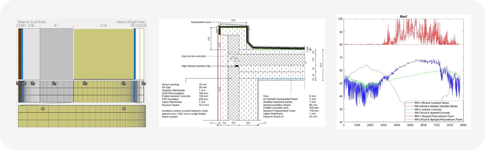
Wall, roof and slab were verified over three years — the roof only stayed mould-free as a warm assembly.
- Wall, roof and floor slab simulated in WUFI, mould growth assessed with the VTT model.
- External wall: wood siding, ventilated air gap, wood-fibre insulation, aerated concrete, EPS and vapour barrier.
- Cold roof assemblies grew mould in the outer layers; the insulation was moved above and below the aerated concrete.
- Slab designed as a shallow slab-on-grade with EPS insulation around and beneath it.
- Thermal bridges calculated in Heat2 for the slab, the intermediate floor and the roof junction.
Mould index
≤ 0.03 VTT model, all layers below 75 % RH
Thermal bridges
0.023–0.062 W/m·K roof junction, floor slab and plinth
05
Thermal comfort
Overheating stays under the FEBY12 limit with fixed shading and orientation-tuned glazing — no mechanical cooling.
- Without shading, every apartment exceeded the permitted overheating hours.
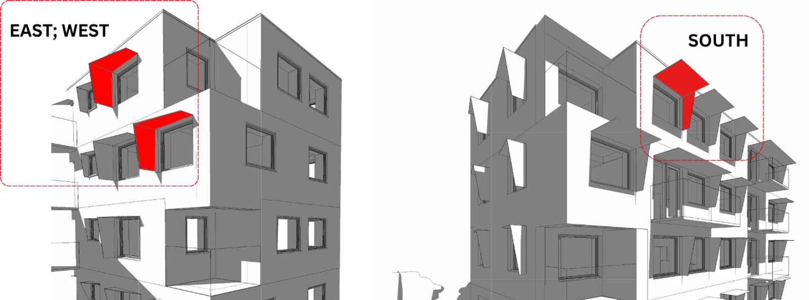
- Overhangs and vertical fins compared on a test zone — overhangs also deflect rain and keep the view.
- Natural ventilation was not counted towards the result, so the margin is on the safe side.
Glazing by orientation
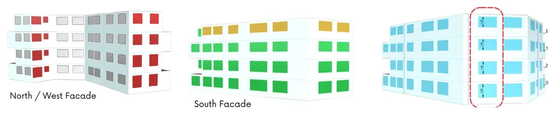
Triple glazing throughout, tuned per façade: high solar transmission to the south for winter gain, low SHGC east and west where low sun is hard to shade, and the lowest U-value to the north.
| Orientation | Floor | U-value W/m²K | SHGC | Tvis |
|---|---|---|---|---|
| North | 1–4 | 0.59 | 0.31 | 0.55 |
| East, West | 1–3 | 0.66 | 0.16 | 0.30 |
| South | 1–3 | 0.68 | 0.30 | 0.55 |
| South, top floor | 4 | 0.65 | 0.21 | 0.51 |
Fixed shading
Overhangs grow from 0.7 m at the bottom to 1.0 m on the top floor, with a vertical fin on the critical east and west windows.
Software
- Rhino
- Grasshopper
- ClimateStudio
- Ladybug
- WUFI
- Heat2
- MATLAB
- Revit
MSc Energy-efficient and Environmental Building Design, Lund University